Continuous-Time Ratiometric
Linear Hall Effect Sensor ICs
A1301 and
A1302
4
Allegro MicroSystems, LLC
115 Northeast Cutoff
Worcester, Massachusetts 01615-0036 U.S.A.
1.508.853.5000; www.allegromicro.com
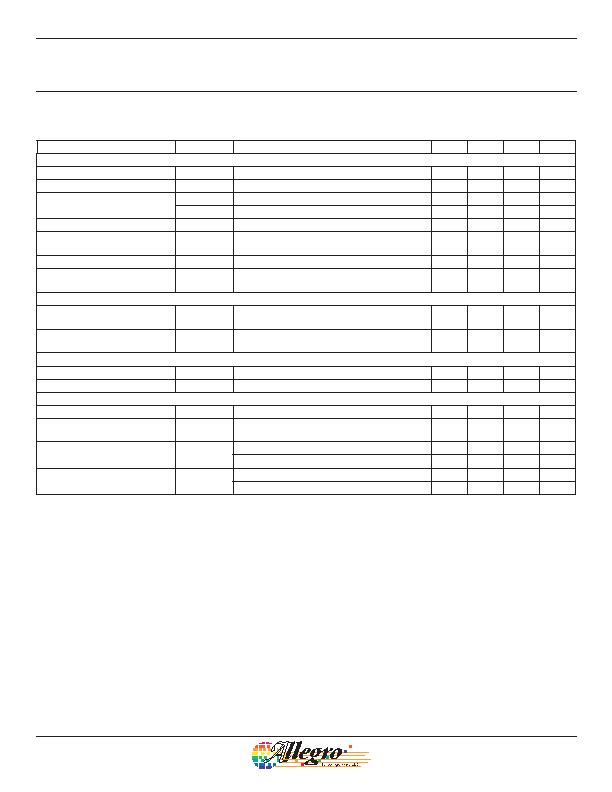
DEVICE CHARACTERISTICS over operating temperature range, T
A
, and V
CC
= 5 V, unless otherwise noted
Characteristic
Symbol
Test Conditions
Min. Typ. Max. Units
Electrical Characteristics
Supply Voltage
V
CC
Running, T
J
< 165癈
4.5 6 V
Supply Current
I
CC
Output open
11 mA
Output Voltage
V
OUT(High)
I
SOURCE
= 1 mA, Sens = nominal
4.65 4.7 V
V
OUT(Low)
I
SINK
= 1 mA, Sens = nominal
0.2 0.25 V
Output Bandwidth
BW
20 kHz
Power-On Time
t
PO
V
CC(min)
to 0.95 V
OUT;
B = ?400 G;
Slew rate = 4.5 V/約 to 4.5 V/100 ns
3 5 約
Output Resistance
R
OUT
I
SINK
d 1 mA, I
SOURCE
e 1 mA
2 5 ?/DIV>
Wide Band Output Noise, rms
V
OUTN
External output low pass filter d 10 kHz;
Sens = nominal
150 糣
Ratiometry
Quiescent Output Voltage Error
with respect to V
CC
1
擵
OUTQ(V)
T
A
= 25癈
?.0 %
Magnetic Sensitivity Error with
respect to V
CC
2
擲ens
(V)
T
A
= 25癈
?.0 %
Output
Linearity
Lin T
A
= 25癈
?.5 %
Symmetry
Sym T
A
= 25癈
?.0 %
Magnetic Characteristics
Quiescent Output Voltage
V
OUTQ
B = 0 G; T
A
= 25癈
2.4 2.5 2.6 V
Quiescent Output Voltage over
Operating Temperature Range
V
OUTQ(DT
A
)
B = 0 G
2.2 2.8 V
Magnetic Sensitivity
Sens
A1301; T
A
= 25癈
2.0 2.5 3.0 mV/G
A1302; T
A
= 25癈
1.0 1.3 1.6 mV/G
Magnetic Sensitivity over
Operating Temperature Range
Sens
(DT
A
)
A1301
1.8 3.2 mV/G
A1302
0.85 1.75 mV/G
1
Refer to equation (4) in Ratiometric section on page 4.
2
Refer to equation (5) in Ratiometric section on page 4.
发布紧急采购,3分钟左右您将得到回复。
相关PDF资料
A1323LLHLT-T
IC SENSOR HALL EFFECT SOT23W
A1351LKTTN-T
IC SENSOR HALL EFFECT 4-SIP
A1354KKT-T
IC SENSOR HALL EFFECT 4-SIP
A1356LKB-T
IC SENSOR HALL EFFECT 3 SIP
A1361LKTTN-T
IC HALL EFFECT SENSOR LN 4-SIP
A1374EKB-T
IC SENSOR HALL EFFECT PREC 3-SIP
A1422LK
IC SENSOR HALL EFFECT AC 4-SIP
A1425LK
IC SENSOR HALL EFFECT AC 4-SIP
相关代理商/技术参数
A130-3
功能描述:SCREWDRIVER SLOTTED 1/8" 4.88" 制造商:klein tools, inc. 系列:- 零件状态:在售 工具类型:螺丝刀 尖头 - 类型:开槽型 尺寸:1/8" 长度 - 插片:3.00"(76.2mm) 长度 - 总:4.88"(124.0mm) 特性:黑色刀头,表面镀铬,口袋夹 重量:0.04 磅(18.14g) 标准包装:12
A1303/4
制造商:DORMER 功能描述:DRILL TAPER SHANK HSS 3/4"
A1303/8
制造商:DORMER 功能描述:DRILL TAPER SHANK HSS 3/8"
A13030
制造商:ABB 功能描述:130-30
A130-30
制造商:ABB 功能描述:130-30
A13030.0
制造商:DORMER 功能描述:DRILL TAPER SHANK HSS 30MM
A13032.0
制造商:DORMER 功能描述:DRILL TAPER SHANK HSS 32MM
A13034.0
制造商:DORMER 功能描述:DRILL TAPER SHANK HSS 34MM
